Main

Tag Archives | furniture

66 Slats / 198 Fasteners

With the white oak slats twisted into shape and drying it was time to layout exactly where each slat was going to attach to the frame and drill holes in the steel frame for where the fasteners would go. It took a few tries to get the spacing right with the dividers, a centreline was scribed and the holes were set with a punch and hammer. The steel base was clamped down to the bed and using a jig that held the drill parallel to the bed 198 holes were drilled through the 3/16″ thick steel. 37.25″ of lineal steel were drilled through over the course of two days.

As the 66 wood slats got fit into place the same drill jig was used to drill out the wood slats for the fasteners.


IMG_5936_opt IMG_5939_opt

0

Twist and Shout!

A little while back we were twisting the 3/4″ thick by 2″ wide by 34″ long white oak slats to make up Dining Table No 1. We were doing this with kiln dried wood, which typically speaking doesn’t steam bend all that well, but given that the most extreme twists for the table are around 45 degrees we tested it out, and it seemed to work without any problems. After one long day and some 70 slats twisted and clamped to the metal base to dry we decided to “test the limits” with the few that remained in the steam box. The slats were steamed for roughly 2-3 hours at 200+ degrees fahrenheit, the results were pretty incredible, to watch the bending happen check out this video.

IMG_5866_opt IMG_5873_opt IMG_5874_opt


0

Magical Metal Work

After a bit of a delay we’re back on to the metal dining table with the twisted white oak slats. I know there have already been pictures of the twisted slats and a video of us “getting our twist on,”  but we’re going to take a step back on this post.

Below are pictures of the metal frame I had fabricated which will hold (frame) 66 twisted white oak slats. In order for the frame to properly hold the twisted wood slats it also requires the metal angle iron to twist from acute to obtuse back to acute, or vice-versa. This is also happening along a curve, two curves actually.

So, in order to ensure as much accuracy as possible (we’re kind of out in space after all) I not only provided a full scale drawing but also made jigs/forms for my metal worker to fabricate the curved twisting angle iron. You can see the angle blocks change from acute to obtuse along the curve, he used these to clamp a strip of cold rolled steel along, and then butt a curved section up to it tacking it along the way. The result was fabricating curved angle iron that changes from acute to obtuse back to acute, or vice-versa.

IMG_5381_opt IMG_5384_opt

There is also a twisted straight section where the angle iron changes from acute to obtuse down the length, no curves, these pieces will make up the triangular ends.

IMG_5395_opt

A lot of head scratching went on with this one, at this point I still had no idea just how the wood slats were going to get fit and attached to the frame. There was also the dilemma of not actually knowing if the piece would be sturdy enough to hold a large piece of glass, but its working in the world of unknown that keeps this exciting.

IMG_5569_opt IMG_1969_opt


0

The Indestructible Miter

Before you get into this, I am sorry, this post is long, it may or may not make a lot of sense, and I am sure a lot of people would argue with what I have said. Carry on.

Indestructible miter. A bold claim I know. Indestructible and miter are words that do not often go together. The miter opened up, this mitre won’t close, why did I choose to use these damn miters, all a lot more common to hear.

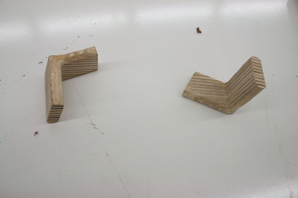
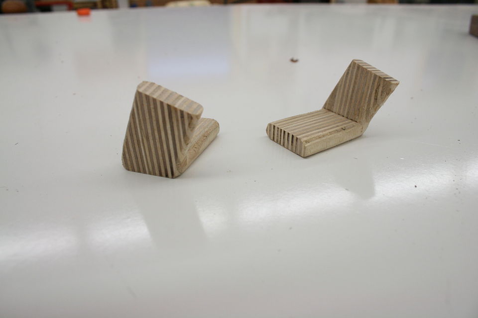
But bear (bare?) with me here, what you are about to see below is an adapted version of a joint that was introduced to me as “the indestructible miter.” Or if you would like to take it down a few notches on the “awesome scale” the plywood L-tenon. It is exactly as it sounds. Plywood and indestructible are again two words we are not used to hearing together, but it is the perfect material for an L-Tenon.

Why you may be asking? Alternating grain direction for maximum strength. It is really just that simple. Miters are difficult to join because of the amount of end grain in the joint (end grain has no glue strength). This is why typically we cut keys or splines in a miter joint is to gain some “face grain glue surface.”

But isn’t half of plywood end grain? Sounds like you are going against your own advice….

You got me, it’s true, but the other half is perfect face grain to face grain glue surface. And the end grain portion on the one side of the miter is the face grain on the other part of the board. Tricky no?

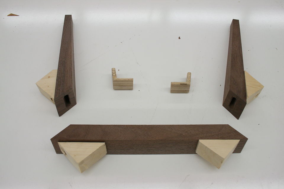
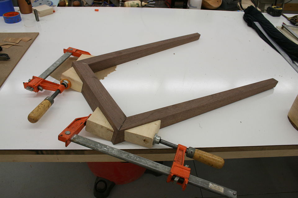
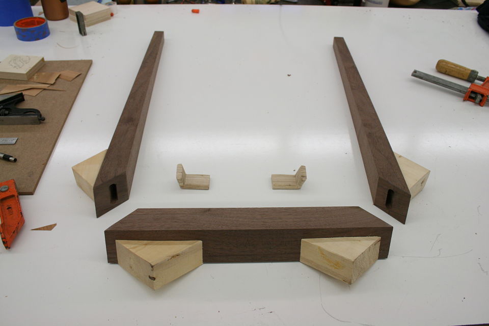
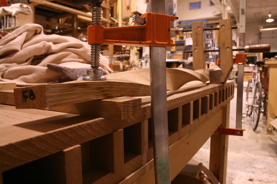
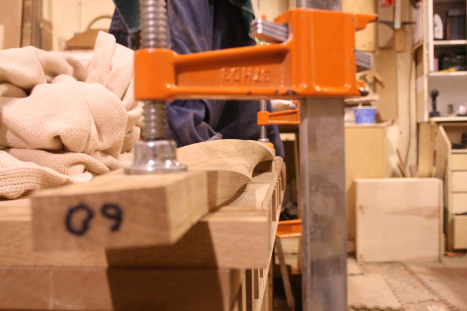
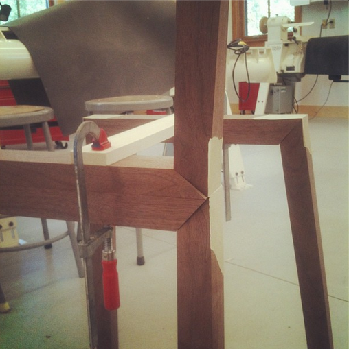
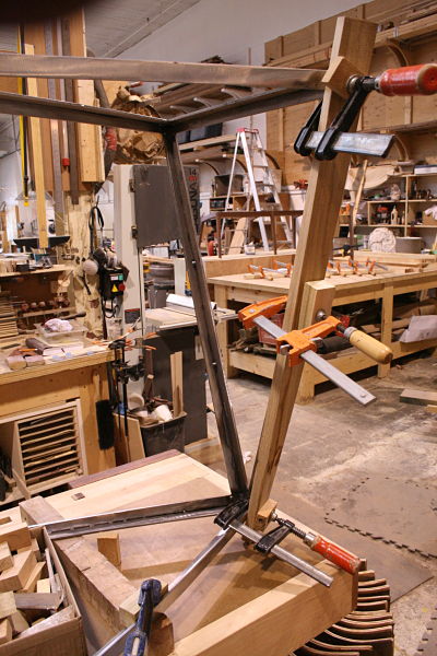
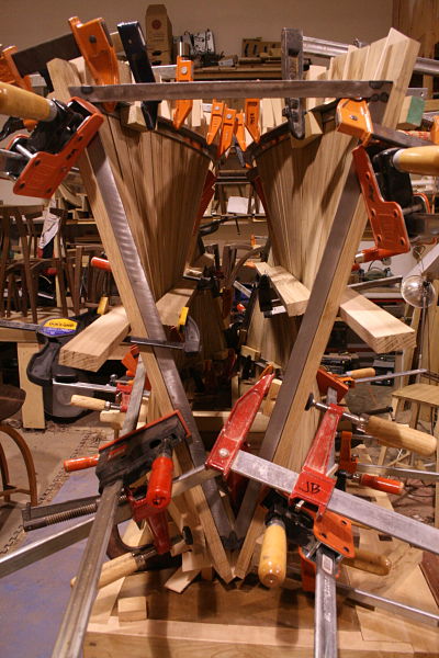
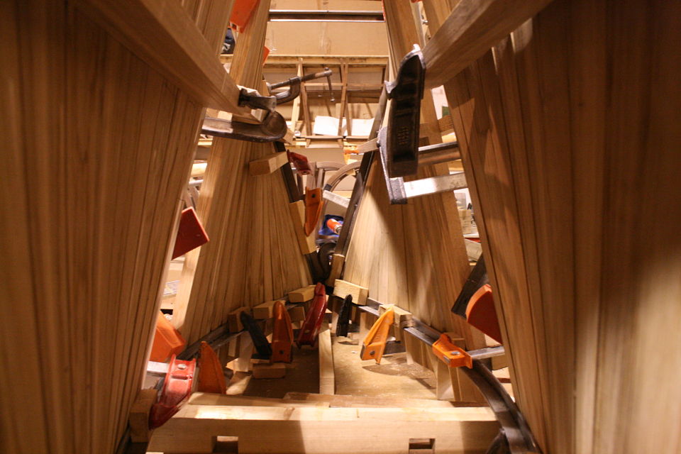
But there’s another part to this equation. Keys / splines and most other miter “joinery” has very little “depth” into the actual boards. This may be okay for little boxes, or a casepiece, but chairs are under stress, a lot of stress, and they need something a little more substantial. The “L-Tenons” allow me to route deep (in this case around 2″) mortises into both parts.  What I end up with is a 2″ worth of tenon (and a longer bit could get me more) into either side of the miter. Quite a bit of depth all things considered. Couple this with the alternating grain and you have a joint that is “indestructible,” relatively speaking anyways.

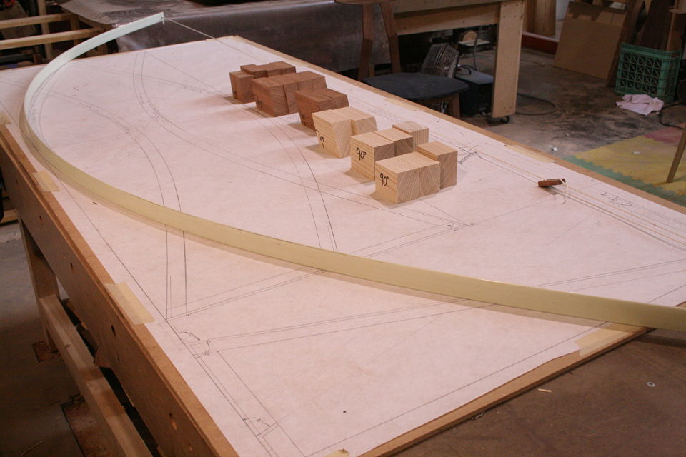
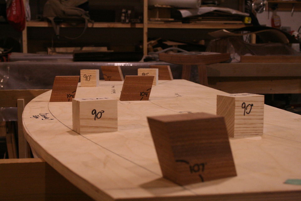
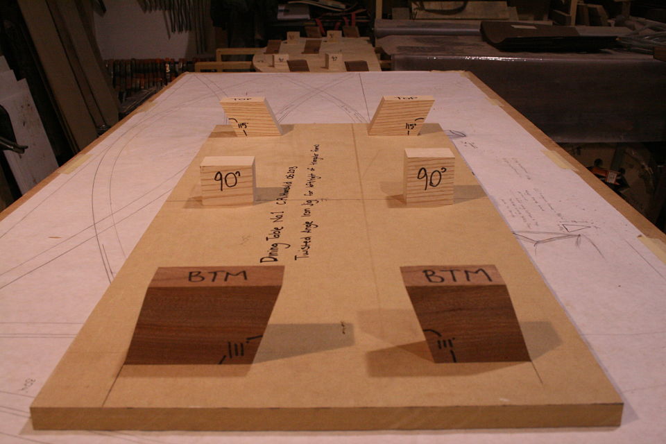
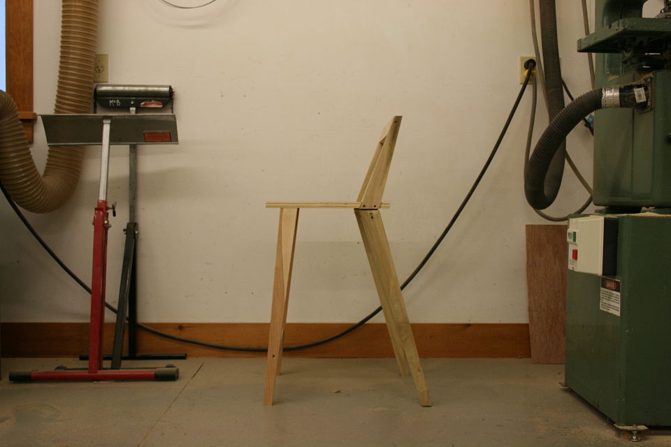
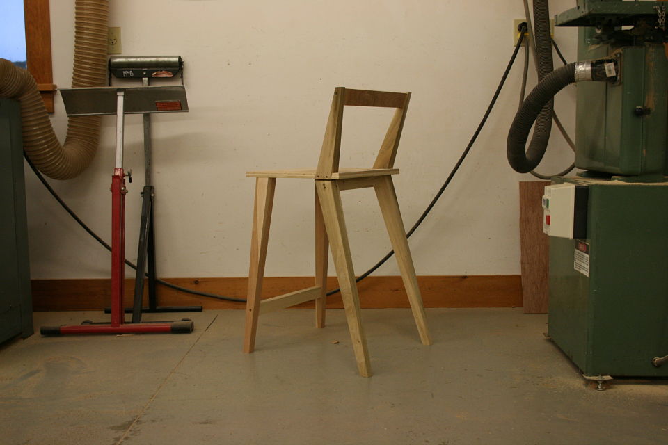
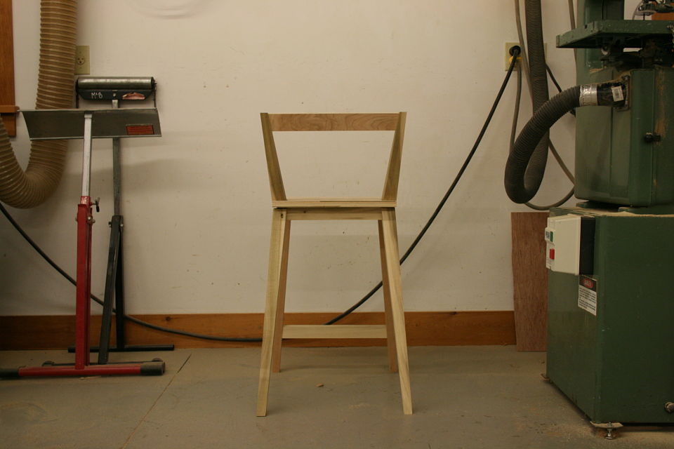
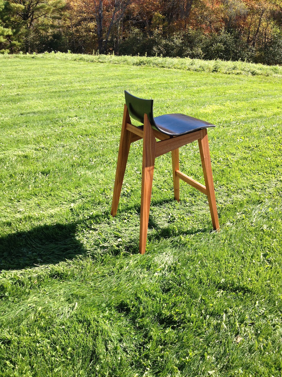
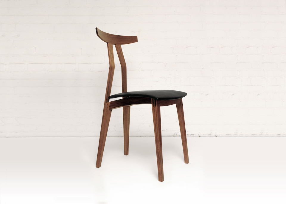
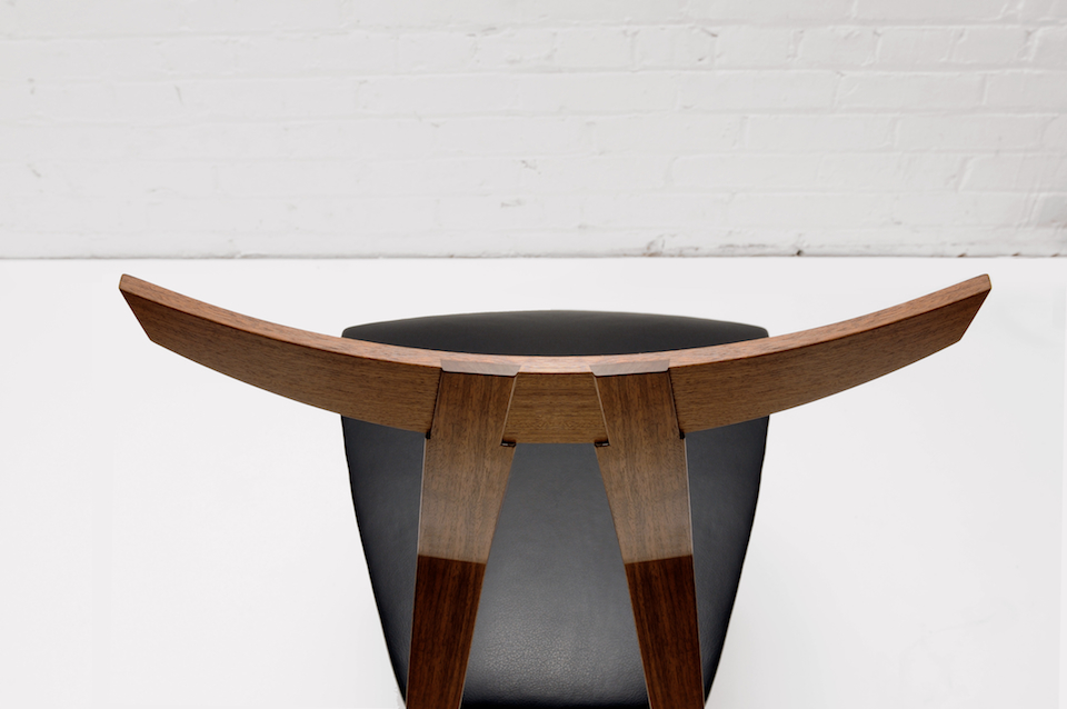
This may be a lot to take in at this point, hopefully the pictures will clear it up some. For the record these are a bit of a variation on your standard “Plywood L-Tenon” as they are obtuse angles and canted as well. Testing as to the actual strength will commence once the stool is together. Stay tuned.

IMG_6368_opt IMG_6367_opt IMG_6362_opt IMG_6360_opt IMG_6358_opt


0

Drawing and Reality

So with the mock-up complete for Bar Stool No. 3 it was time to move on to a more detailed full scale drawing. Below is a drawing that the more I tried to simplify it the more complicated it appeared. The result was my brain getting pretty mushy and working on something else for the morning (see the post about dodecahedrons).

In the end I needed to trust the angles and dimensions I had laid out and went to cutting the compound mitred frames that will make up this stool. The picture at the bottom is with the angles cut and pieces of tape wrapped around the outside of the miter to see how everything fits together. I should have been able to visualize this from my drawing (maybe?) but was pleasantly surprised when I began piecing the parts together and revealed the “double mitre” joint that will be visible from the back of the stool.


0

Mocking Up Bar Stool No. 3

While co-teaching the chair making course at the Center for Furniture Craftsmanship I got an opportunity to design a speculative piece, something I rarely have the opportunity to do throughout the rest of the year while commissioned work is on the go.

Below are pictures of the first mockup for a new bar stool design. I usually begin my design process for seating objects by going from a sketch to a full size drawing. The full size drawing doesn’t need to be complete from all views, but at least have basic dimensions, shapes and angles roughed out. I then make the first mockup with whatever materials are lying around, in this case plywood, poplar, screws and hot glue to get a rough idea of proportions, shapes, heights and angles. The mockup is a tool used to go back and refine the drawing, see the idea in three-dimension and begin to work through what the construction / process of the piece might look like. It’s always best if you can sit in the mock up to gauge comfort of heights and angles, sometimes additional props or stilts might be required.

Things I learnt from this mockup….

I felt the weight of the legs was a bit heavy, so they have been taken down in dimension on the first iteration. Part of this might be the thickness of the plywood seat I had available which is a bit thinner (lighter) then I have planned. I also wasn’t a fan of the seat sticking out past the back legs, so that has been reworked. The footrest has been raised, and the front legs have a wider stance to give the seat some splay which will be more cohesive with some of the other tapered forms found throughout the piece. Now to sort out the construction…

IMG_6322_opt IMG_6324_opt IMG_6326_opt

1

Chair Making at the Center For Furniture Craftsmanship

A couple months ago now I received a phone call from Peter Korn wondering if I would be interested in co-teaching a Chair Making class with Jeff Miller this September-October. Having been fortunate enough to have taught at the Center for Furniture Craftsmanship (CFC) the previous two summers I thought I was being “given the summer off.” I was thrilled to be presented the opportunity and excitedly accepted the job offer.

IMG_6280EDIT_opt


It was a hectic two weeks but a helluva lot of fun. Seeing people starting to “get it” is a pretty remarkable thing to watch and even more rewarding when you played a part in getting them there. I had a great time teaching with Jeff Miller (check out his work and blog at www.furnituremaking.com) and learnt a lot from this chair making (and teaching) veteran. He was very encouraging to me as a teacher, I am still learning at this teaching gig so every bit of advice is helpful.

As for the students I couldn’t have been more impressed with what they were able to accomplish in just two weeks. Coming from a wide array of backgrounds these 12 gentleman powered through what is arguably one of the hardest challenges in woodworking, the chair. Kudos to all of the students who made the class what it was, Jeff, Karl the awesome assistant and the CFC for hosting. Here’s to good times and hopefully more to come.

IMG_6313_opt IMG_6276_opt IMG_0677_opt


0

Let the twisting begin!

Dining Table No. 1 is going to consist of 66 twisted wood slats twisted to 16 different angles. We are using 3/4″ thick kiln dried white oak that will be steamed at 200+ degrees fahrenheit for around 2 hours. Here is a video of the twisting in action. Clamps, we also needed a lot of clamps, seriously.

IMG_5850_opt IMG_5863_opt IMG_5878_opt


3

Dining Chair No. 6

Dining Chair No. 6 by Reed Hansuld is in the process of being posted online, enjoy the taster down below. Shown in walnut with a black leather seat.

DSC_6168_opt DSC_6224 copy_opt

0

Dining Table No. 1 Sketch

Incorporating metal into my furniture is something I have a growing interest in as of late. It opens new doors for pushing the boundaries of traditional construction and forms. Below is a sketch of a dining table commission, it will at some point be a metal frame that will house 66 twisted wood slats in the weeks to come. Stay tuned for updates of the process and headaches that will surely follow.

IMG_4695_opt

1

Powered by WordPress. Designed by Woo Themes